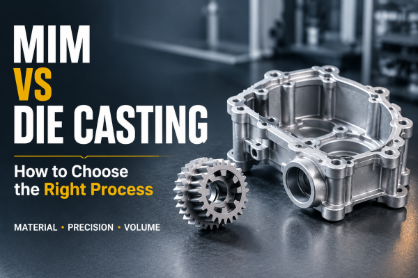
If you're sourcing a manufacturing process for a small, geometrically complex metal part that also demands high precision, "Metal Injection Molding," or MIM, is likely on your shortlist. In short, MIM blends metal powder with a binder into a "feedstock," shapes it much like plastic injection molding, then sinters the part to remove the binder and densify it into a finished metal component. Within the broader powder metallurgy family, MIM is the process built specifically for parts that are too complex or too costly to machine conventionally. By the end of this guide, you'll understand how MIM parts are actually made, what materials are available, the tolerance and typical lead times you can expect, and where MIM fits best.
What Exactly Is MIM
Think of MIM as plastic injection molding and powder metallurgy combined: injection molding contributes the freedom to form complex shapes in a single step, while powder metallurgy contributes the ability to use metal powder as the raw material. Together, they let MIM produce near-net-shape parts — geometry that might take five or six machining operations to reproduce conventionally comes out of the mold in one shot, needing little to no secondary processing. What does that mean in practice? When your part is geometrically complex, produced at meaningful volume, and needs dimensional consistency, MIM is often more cost-effective than machining each part individually or tooling up for die casting. That said, "more cost-effective" isn't absolute — it depends on the part's structure, material, and volume, which is exactly what most customers want to nail down early in the conversation.
From Metal Powder to Finished Part: The Five-Step Process
Step 1: Feedstock Preparation
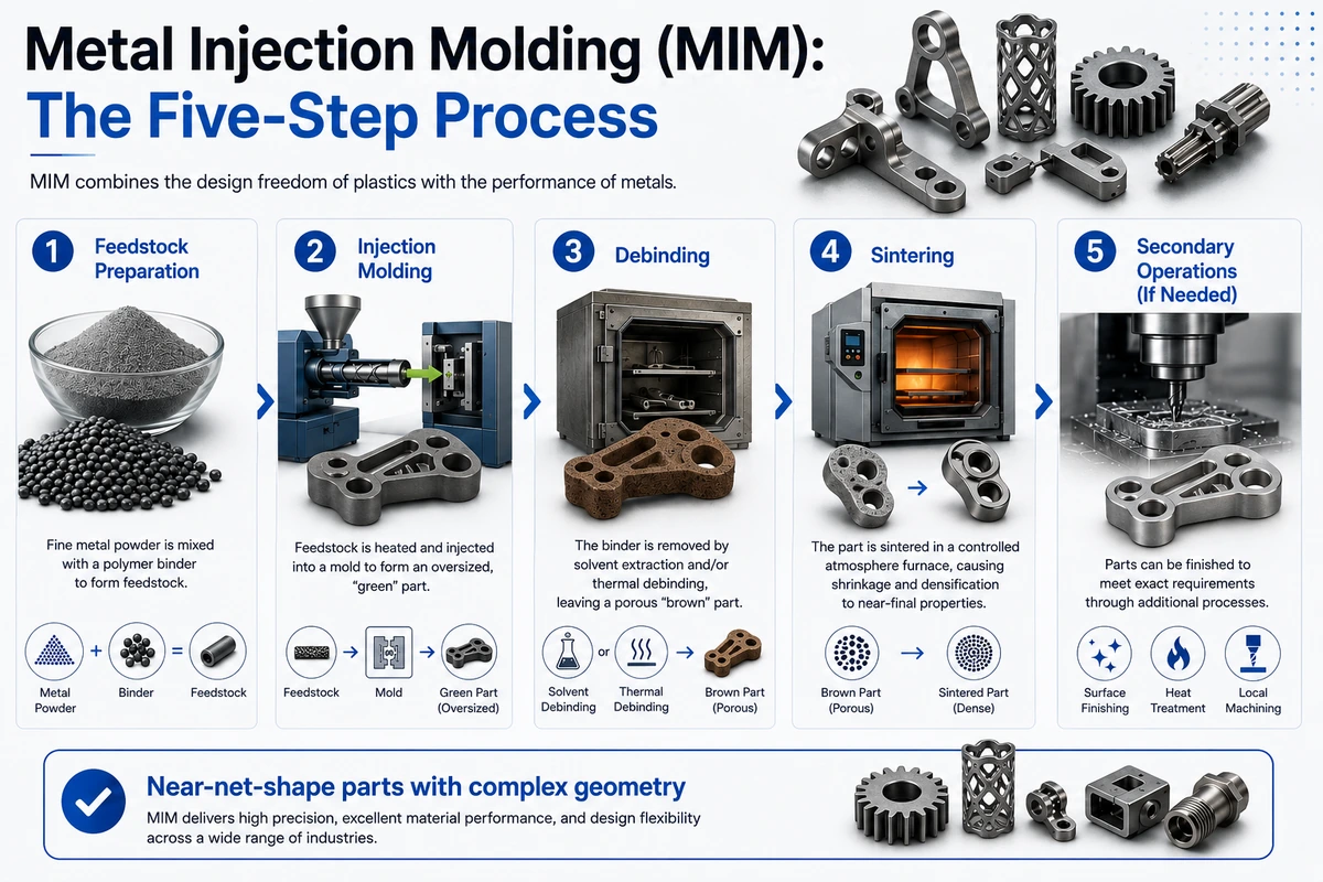
Fine metal powder — typically a few microns to about 20 microns in particle size — is blended with a binder (usually thermoplastics, waxes, and other organic components) in a specific ratio to form the "feedstock." This step looks simple, but the powder's particle characteristics and the binder formulation directly determine whether molding and sintering will run consistently downstream.
Step 2: Injection Molding
The feedstock is fed into equipment much like a standard plastic injection molding machine and injected into a mold cavity, forming a "green part" — same shape as the final part, but noticeably oversized. That oversizing is intentional, not an error: the part will shrink substantially during sintering, so the mold cavity has to be built larger to compensate in advance. Mold design and injection parameters at this stage largely determine what precision the final part can achieve.
Step 3: Debinding
Heat or solvent treatment removes most of the binder from the green part, leaving a porous "brown part." This step has to be done gradually — debinding too fast or incompletely makes the part prone to cracking or distortion, and it's one of the more failure-prone stages in the whole process.
Step 4: Sintering
The brown part goes into a sintering furnace under controlled atmosphere, where high heat drives solid-state diffusion to densify the part — the remaining binder is fully removed, powder particles bond together, the part shrinks toward its final dimensions, and it develops its target mechanical properties. A commonly cited industry figure is that MIM parts undergo roughly 15% to 20% linear shrinkage during sintering, though the exact number varies meaningfully with material composition, powder characteristics, and sintering parameters. Actual shrinkage in production should be confirmed through process engineering testing on the specific material and tooling involved.
Step 5: Secondary Operations (If Needed)
Some parts are ready to use straight out of the furnace. Others need surface finishing, heat treatment, or local precision machining to meet specific appearance or functional requirements.
What Materials Can MIM Use
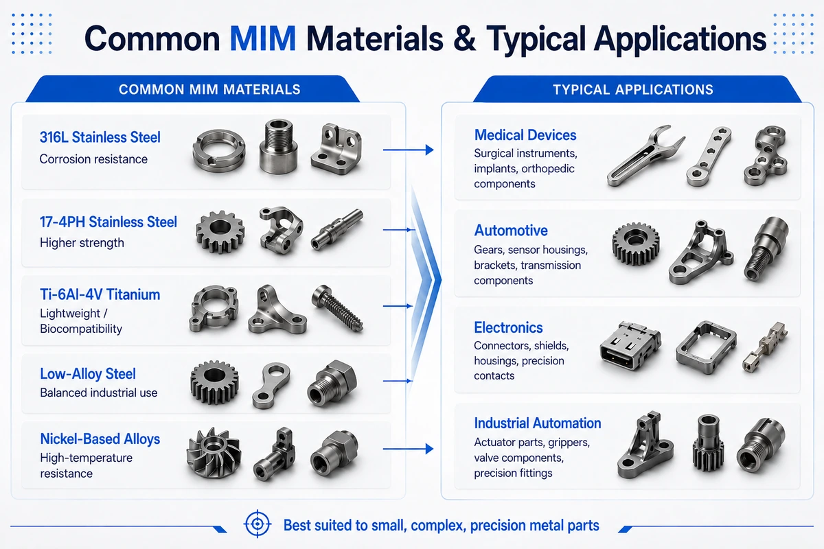
MIM's material range is actually fairly broad. Materials we commonly work with include 316L stainless steel, 17-4PH stainless steel, Ti-6Al-4V titanium alloy, low-alloy steel, and nickel-based alloys such as Inconel, among others — see our full metal injection molding capabilities for details. 316L offers strong corrosion resistance and is common in medical and consumer products; 17-4PH offers higher strength, suited to parts with structural demands; titanium alloy is lightweight with good biocompatibility, often used in medical and select high-end applications; low-alloy steel offers well-balanced overall properties and sees frequent use in industrial structural parts; nickel-based alloys stand out for high-temperature and corrosion resistance, commonly used in demanding operating conditions. If your project calls for a different grade, check with our engineering team — we can evaluate feasibility case by case. One thing worth flagging: the specific tensile strength, hardness, and elongation each material achieves can swing meaningfully depending on sintering parameters — that's not us withholding information, it's inherent to how MIM works. The same material can show a difference of tens to over a hundred MPa depending on sintering temperature and time. The more reliable approach is requesting tested data for the specific grade and process parameters early in your project, rather than applying a number from a paper or an isolated data point.
How Big and How Precise Can MIM Parts Be
Based on publicly available industry data, MIM is best suited to small-to-mid-size parts, with weight typically ranging from 0.1 g to 300 g — the most common and cost-effective range being roughly 1 g to 50 g — and dimensions generally under 150 to 200 mm. On tolerance, the widely accepted industry level is around ±0.3% to 0.5% of the part's dimension — for example, a 25 mm dimension would carry a tolerance of roughly ±0.075 to ±0.125 mm. For small precision parts with relatively simple structures and geometry that supports even shrinkage during sintering, our actual tolerance capability can reach the ±0.03mm range — noticeably tighter than typical industry levels. That said, this isn't achievable on every part; it depends on the part's size, geometry, and how controllable the sintering process is for that specific shape. For critical dimensions requiring tighter control, secondary machining is typically still needed as a backstop. The tolerance actually achievable on a specific part still depends on an engineering review of your drawings and process. You can find our complete tolerance, capacity, and material data on our metal injection molding capabilities page.
How Long Does MIM Tooling and Production Typically Take
MIM requires dedicated tooling upfront, which factors into the overall timeline. Based on our actual production scheduling, tooling development typically takes 20 to 30 days, and once in volume production, lead time runs about 10 to 20 days — the specific timeline varies with part complexity, material, and batch size. We'd recommend confirming exact scheduling with our engineering team early in your project.
Where Is MIM Used
Complex geometry, high precision, and meaningful volume — wherever those three line up, you'll typically find MIM at work: small structural components in medical devices, sensors and select structural parts in automotive applications, connectors and precision enclosures in electronics, and drivetrain components in industrial automation equipment are all common use cases. Requirements around materials, certifications, and tolerance vary significantly by industry — medical applications often need to account for biocompatibility and traceability, while electronics applications tend to prioritize dimensional consistency and cosmetic quality. We go deeper into what these parts look like industry by industry in our MIM part design guide.
How Does MIM Compare to Other Processes
MIM isn't the only route to a precision metal part — compared with die casting and CNC machining, each process has its own sweet spot. Die casting handles a wider size range and very large volumes well; CNC machining offers more flexibility on materials for single units or small batches. If you're stuck deciding which process fits your project, our MIM vs. die casting comparison breaks it down across material, precision, and volume economics. If you already have drawings in hand, send them to our engineering team — we'll get back to you with feedback based on manufacturability. Discuss Your Application →
References & Sources
1. Metal Injection Molding — Metal Powder Industries Federation (MPIF)
2. What is MIM? — Metal Injection Molding Association (MIMA), an MPIF affiliate
3. An Overview of the Metal Injection Moulding Process — PIM International
 Have a Custom Manufacturing Project?