Introduction
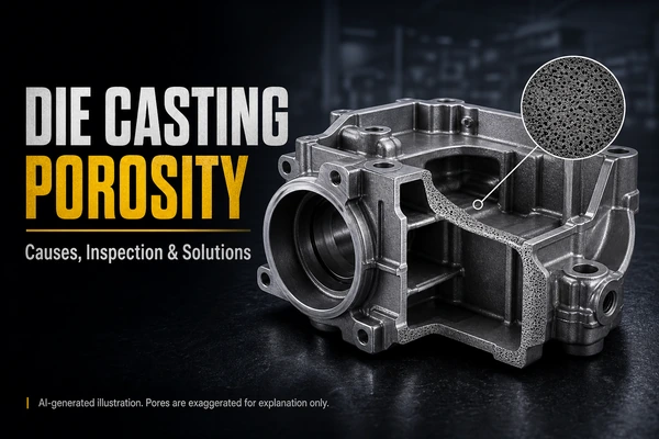
Die casting porosity is one of the most common concerns in aluminum high pressure die casting, but it is often discussed too vaguely. In real projects, the issue is not simply whether a casting contains pores. The more useful question is where the porosity appears, how large it is, and whether it affects sealing, CNC post-machining, cosmetic finishing, or structural reliability.
This article focuses on aluminum HPDC parts such as ADC12, A380, and AlSi9Cu3. That scope matters. Porosity control in gravity casting, low-pressure casting, and sand casting follows a different logic, so the discussion below is intended for aluminum high pressure die casting rather than for every casting process.
What Die Casting Porosity Means in Aluminum HPDC
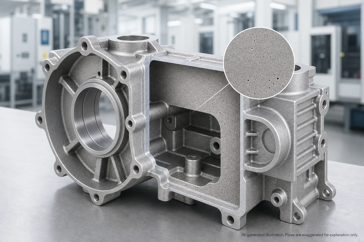
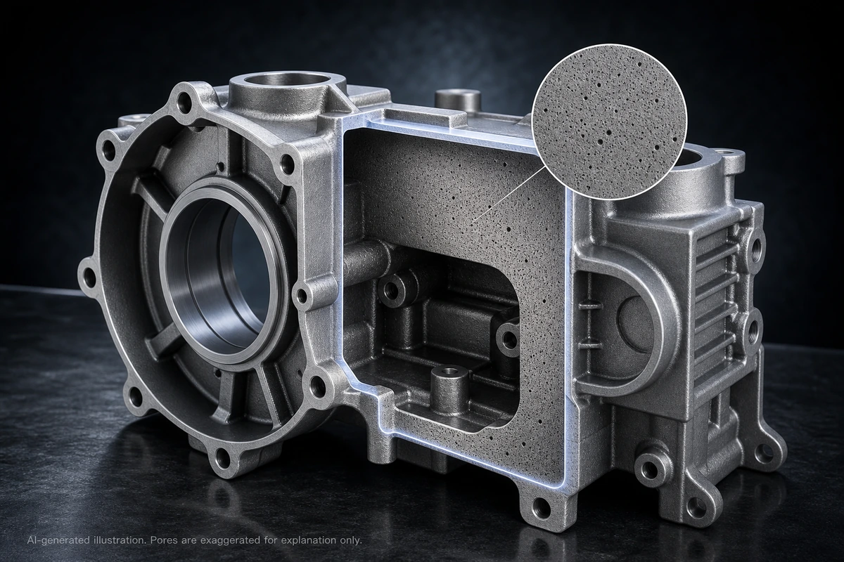
Porosity refers to voids inside the casting or just below the surface. Some pores stay hidden unless the part is sectioned or checked by X-ray or CT. Others do not become obvious until after trimming, blasting, polishing, coating, leak testing, or CNC machining.
For engineering review, it is better to separate porosity into two dimensions instead of mixing them together.
| Classification |
Meaning |
Typical examples |
| Formation mechanism |
How the pore formed |
Gas porosity, shrinkage porosity |
| Exposure state |
How the pore appears in the part |
Internal, near-surface, open porosity |
That distinction matters because gas porosity and shrinkage porosity do not always need the same corrective action, and a hidden internal pore is not judged the same way as an open pore on a sealing face.
Gas Porosity vs Shrinkage Porosity
In aluminum HPDC, gas porosity is commonly associated with air entrapment, incomplete venting, vapor from die lubricant, low vacuum efficiency, or gas carried in the melt. Shrinkage porosity is more closely tied to local hot spots, uneven solidification, weak feeding conditions, or poor pressure transfer during the final stage of solidification.
| Porosity type |
Typical cause |
Typical appearance |
Main risk |
| Gas porosity |
Air entrapment, poor venting, lubricant vapor, gas in melt |
More rounded voids |
Leak paths or pores exposed after machining |
| Shrinkage porosity |
Local hot spots, uneven solidification, poor feeding, weak intensification transfer |
More irregular voids |
Structural weakness or sealing risk |
Why Die Casting Porosity Matters in Real Parts
A small isolated pore on a non-critical cosmetic corner may be acceptable. The situation changes when porosity appears in a pressure wall, sealing face, threaded hole, O-ring groove, machined datum, or fatigue-sensitive section.
| Part feature |
Why porosity becomes a problem |
| Sealing wall or sealing face |
It can become a leak path |
| Machined surface |
Hidden pores may open after CNC machining |
| Threaded area |
Local strength and thread consistency may drop |
| Cosmetic face |
Pinholes or pits become visible |
| Fatigue-sensitive section |
Pores can act as stress concentrators |
Why CNC Machining Often Exposes Porosity
One of the most common buyer complaints is that the raw casting looked acceptable, but pores appeared after machining. That happens because the cast skin can hide voids that sit just below the surface. Once the sealing face, counterbore, thread location, or mounting pad is machined, those voids may open.
For parts with sealing lands, threaded ports, O-ring grooves, or flatness-critical faces, the post-machining condition should be reviewed during tooling development, not only after the first leak failure.
Why Porosity Can Become a Finishing Problem
Porosity is not only a leak issue. It can also become a finishing issue. A casting that looks acceptable before finishing may show visible defects after anodizing, powder coating, painting, plating, polishing, or blasting.
| Surface finish |
Typical risk |
| Powder coating or baking paint |
Pinholes or blistering from gas release |
| Anodizing |
Pores, dark spots, and color variation become more visible |
| Plating or chemical treatment |
Chemicals can remain in pores and affect appearance or corrosion resistance |
| Polishing or blasting |
Near-surface pores may open into pits or rough spots |
What Causes Die Casting Porosity in Production
In HPDC, porosity is usually not caused by one isolated mistake. Most failures come from several smaller conditions acting together: part geometry, flow path, venting, thermal balance, melt condition, shot profile, and intensification behavior.
It is also important not to overstate the role of hydrogen. In aluminum alloys, hydrogen is the most important dissolved gas to watch, but in aluminum HPDC, gas porosity is not explained by hydrogen alone. High-speed filling can entrain air, venting can be insufficient, die lubricant can create vapor, and vacuum performance can vary shot to shot.
| Process area |
Common problem |
Main porosity risk |
Typical control action |
| Part geometry |
Sudden wall change or hot spot |
Shrinkage porosity |
Smooth wall transitions |
| Gate and runner design |
Unstable flow front |
Gas porosity |
Optimize gate and runner layout |
| Overflow and venting |
Poor evacuation of cavity air |
Gas entrapment |
Improve vent slots and vacuum layout |
| Melt management |
High gas pickup or poor cleanliness |
Gas-related porosity |
Control melt temperature and degassing |
| Shot profile and intensification |
Weak pressure transfer |
Mixed porosity risk |
Optimize shot curve and intensification timing |
| Thermal balance |
Slow freezing zone |
Shrinkage or mixed porosity |
Improve local cooling and die balance |
How Manufacturers Inspect Die Casting Porosity
Inspection method is not the same thing as acceptance standard. A supplier may complete X-ray or CT inspection and still end up in a dispute if the drawing never defined where pores are allowed and what level is acceptable.
The right inspection route depends on the real function of the part.
| Inspection method |
Best used for |
Main limitation |
| Visual inspection |
Open pores and obvious surface defects |
Cannot show internal porosity |
| Sectioning or metallography |
Defect morphology and local structure |
Destructive and local only |
| X-ray radiography |
Internal porosity screening in production |
Less detailed than CT for complex geometry |
| CT scanning |
3D porosity distribution and failure analysis |
Higher cost and slower throughput |
| Leak testing |
Direct sealing verification |
Does not explain the root cause by itself |
| Acceptance item |
Why define it early |
| Allowed porosity location |
Risk depends on where the pore appears |
| Maximum pore size and quantity |
Prevents vague pass or fail disputes |
| Required X-ray level or customer standard |
Keeps radiographic judgment consistent |
| CT resolution and region of interest |
Avoids comparing scans with different detail levels |
| Leak test pressure, hold time, and leak rate |
Makes sealing acceptance measurable |
| Post-machining or post-finishing condition |
Final function may change after secondary operations |
Practical Solutions for Die Casting Porosity
The most reliable solution is not one dramatic parameter change. It is a coordinated control plan that starts before the mold is frozen.
| Control direction |
Practical action |
| Tool design |
Optimize gate, runner, vent, overflow, and vacuum design |
| Filling behavior |
Adjust switchover and final fill behavior |
| Intensification |
Verify pressure, timing, and biscuit stability |
| Thermal control |
Improve local cooling and die heat balance |
| Melt management |
Control scrap ratio, melt temperature, degassing, and cleanliness |
| Lubricant control |
Control spray amount, location, and dry-off time |
| Corrective option |
Use vacuum impregnation only when application and customer approval allow it |
Vacuum impregnation can help with micro-leak paths in some castings, but it should be treated as a supplementary corrective option, not a substitute for poor upstream process control.
Final Takeaway
Die casting porosity in aluminum HPDC should be discussed in terms of function, location, cause, and verification, not as a generic defect label.
A real manufacturing discussion should answer four questions clearly: what type of porosity is involved, where it creates real risk, what process actions are being used to reduce that risk, and how the final part will be accepted after machining, finishing, or leak testing.
Need Help Reviewing Porosity Risk in an Aluminum Die Cast Part?
If you are sourcing an aluminum die cast housing, cover, pump body, or other HPDC part with sealing faces, threaded holes, or CNC-machined areas, send us your 2D drawing, 3D file, alloy, surface finish requirement, and annual volume. We can review the porosity-sensitive areas before tooling starts and suggest a more practical die casting and machining plan.
FAQ
Q: Is all die casting porosity a scrap issue?
A: No. The risk depends on where the pore is located and what the part needs to do.
Q: Does aluminum die casting porosity come mainly from hydrogen?
A: Not in every case. Hydrogen matters, but air entrapment, venting, die lubricant vapor, vacuum performance, and shot behavior are also major factors in HPDC.
Q: Can vacuum impregnation solve porosity?
A: It can help seal some micro-leak paths, but it is not a universal fix.
Q: Why does porosity show up after CNC machining?
A: Because machining removes the cast skin and can open voids that were hidden just below the surface.