Metal Injection Molding Design Guide Before Tooling
Check wall thickness, demolding direction, sintering supports and functional drawing requirements before tooling. Prepare a MIM DFM review covering geometry, processing and sample validation.
Check wall thickness, demolding direction, sintering supports and functional drawing requirements before tooling. Prepare a MIM DFM review covering geometry, processing and sample validation.
When designing a metal injection molding (MIM) part, first identify the features that control assembly, sealing, movement or load bearing. Then review thickness transitions, mold release, sintering support and how critical dimensions will be produced. These checks help determine which features can be formed directly, which need geometry changes or additional mold mechanisms, and which should be machined after sintering.
Coming out of the mold intact does not mean a part meets its final requirements. The molded green part still has to be handled, debound and sintered. It shrinks as it densifies during sintering, and unsupported or slender features may distort. This guide covers design for manufacturability (DFM) review before tooling, with checks you can apply to CAD models and drawings. For an overview of the process, see what metal injection molding is.
Before changing the geometry, establish how the part works. The relationship between a locating hole and a mounting surface, the contact position of a locking face, or the flatness of a sealing surface often deserves closer control than tight tolerances on every external dimension. Show critical dimensions, their datums and acceptance requirements on the drawing. Mold design, sintering and secondary operations should all address these functional requirements.
For example, a thin-walled housing can meet its overall dimensions while a locating hole is out of position relative to the mounting datum. Define the hole position and datum clearly so the manufacturer can evaluate direct molding, post-sintering sizing or local finish machining. Specify the material grade and final condition early. Include heat treatment or surface treatment in the review if it may affect mating dimensions.
Create CAD sections through boss roots, rib intersections and transitions between thick and thin features. Mark the local thickness and the adjacent wall thickness. Then identify areas that cannot change because of loading, fit or assembly clearance. This separates essential geometry from thick areas that can be redesigned, rather than relying on the external shape alone to decide where to remove material.
Whether cored holes, cavities or ribs can reduce a thick section depends on the load path and available assembly space. Where a joint cannot be thinned, consider a gradual transition or fillet. After adding ribs, check whether the rib roots and existing wall create another thick area. Fillets must also fit within the mating clearance without shifting the intended contact position.
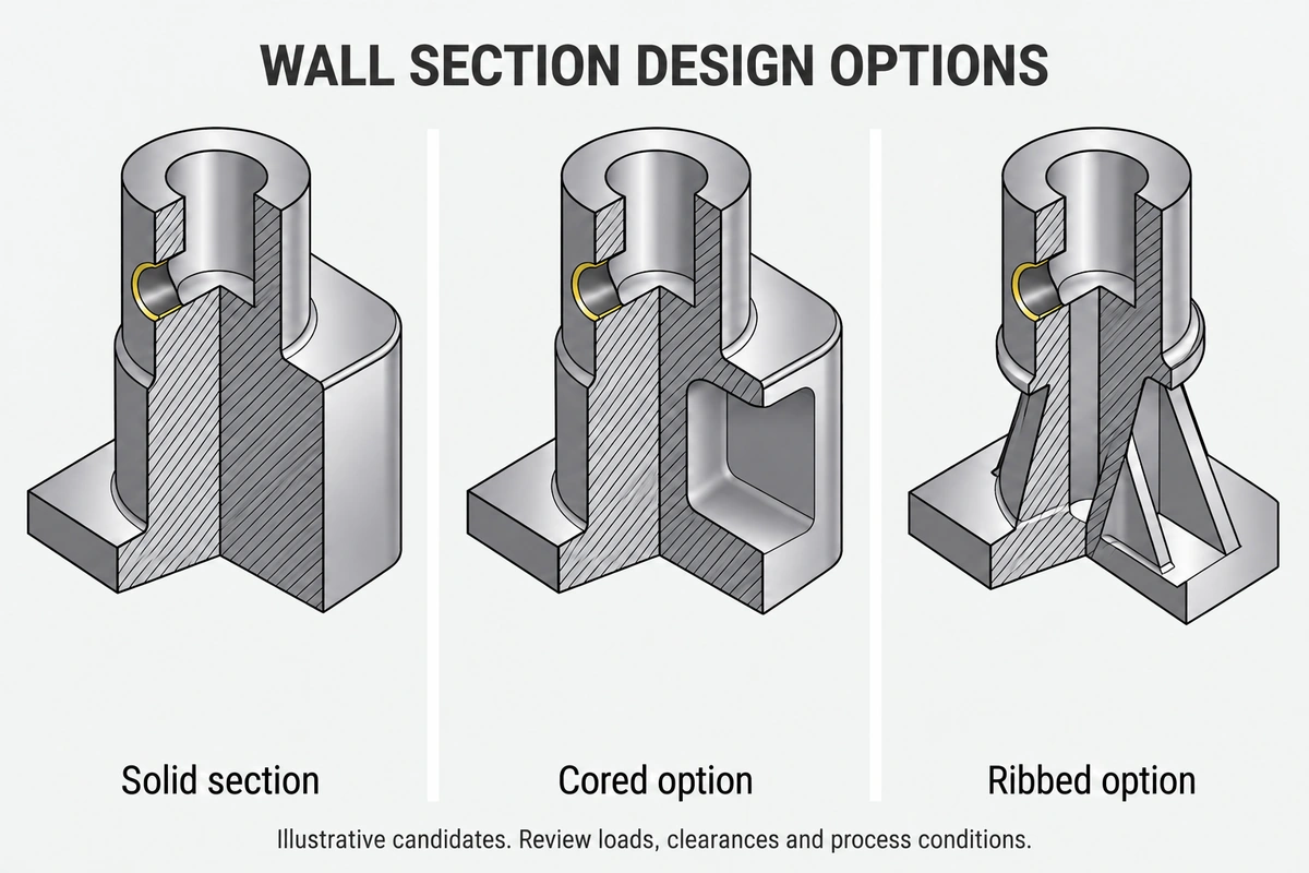
Thin walls generally use less material and shorten the debinding path, but making them too thin can make filling, green part ejection and handling more difficult. Thick sections require a review of the binder removal path and differences in shrinkage relative to surrounding features. Neither pursuing the thinnest possible wall nor using a dimension chart without material, feature length and process context is enough to make the design decision.
| Geometry | CAD check | Information for review |
|---|---|---|
| Thick section joined to a thin wall or arm | Joint section and room to reduce thickness | Key sections, areas that cannot be changed and proposed gradual transitions |
| Solid boss or intersecting ribs | Local thickness at boss and rib roots | Local sections, joint loading and permitted changes |
| Functional surface near a sharp internal corner | Whether a fillet enters the contact or mating area | Contact surfaces, mating clearance and space for the fillet |
These changes provide a starting point for DFM discussion. Check that the revised geometry still performs its function, and have the manufacturer review its effect on molding, debinding and sintering. MIMA's guidance on complex MIM designs also considers wall thickness, ribs and sintering support together.
Changing a hole's orientation can change how it is produced in the mold. A hole aligned with the mold opening direction is usually easier to form with a core. Side holes, intersecting internal holes and slots obstructed by other features need a review of core withdrawal, core support and whether the shutoffs where cores meet can seal reliably and control flash. Deep, narrow blind holes also require a check of core stiffness and demolding conditions. If function allows, compare reorienting the hole or making it a through hole before tooling.
Some undercuts and side features can be formed with slides, side actions, movable inserts or collapsible cores. Evaluate the proposed arrangement against demolding direction, sintering shrinkage, mold wear, flash risk and mold life. If several moving mechanisms are needed, compare direct molding with local secondary machining for cost and reliability. The CAD shape alone does not establish whether the part is suitable for production.
Review draft for each part. Feedstock, core withdrawal length, surface texture and ejection method all affect the requirement. Some wax-containing feedstocks may allow very little draft under suitable conditions, while other geometries need more. For mating holes or walls, specify the effective mating length and dimensions. The mold design must allow the green part to release while meeting the final assembly requirements.
Choose how to produce threads based on their function. Some internal and external threads can be molded directly, while internal threads with tighter requirements may be better tapped after sintering. Compare the options once the thread class, effective length, direction and mold design are defined.
For long cantilevers, thin flat sections with large unsupported spans, and slender bosses, first consider how the green part will be handled and placed. Sintering also requires control of sag caused by gravity. Review the part's orientation, available support surfaces and areas where contact marks are unacceptable. Using a flat sintering setter or a dedicated support fixture affects manufacturing cost and handling requirements.
The support arrangement must also allow shrinkage. Contact surfaces, friction and geometric constraints can affect movement as the part shrinks. Check that the support does more than hold an overhang in the CAD model: it must not obstruct shrinkage. If function allows, compare adding coplanar support areas, reducing unsupported spans or changing the ribs. If the geometry must remain unchanged, evaluate dedicated support and subsequent sizing during quotation and sample trials.
OptiMIM's design guidance treats cantilever sag, support and demolding as separate review items. These principles help identify risks; the final orientation and support arrangement still need validation with the actual part.
The gate controls where feedstock enters the cavity and its flow path, and leaves a gate vestige that needs attention. Parting lines and ejector locations can also affect appearance and local contact. Before tooling, show which marks are acceptable on sealing surfaces, sliding surfaces, assembly datums and surfaces with demanding appearance requirements, along with the applicable limits.
The supplier proposes gating, parting and ejection arrangements; the product designer defines functional restrictions and acceptable limits. For example, establish whether ejector marks are allowed on a mounting surface, whether a parting line may cross a sealing contact area, and whether finish machining is permitted after gate removal. If the restrictions conflict, compare moving the parting line, changing local geometry or adding a secondary operation.
The product drawing normally specifies the final part dimensions, while the mold cavity needs shrinkage compensation suited to the feedstock and process. BASF Catamold describes this relationship using an Oversizing Factor (OSF). Oversizing is part of mold design, but a single general factor cannot ensure every hole position, flatness requirement and mating dimension. Asymmetric sections, support conditions and subsequent treatments can still affect the final result.
Define which features will remain as sintered, which may be sized, and which will have allowance for reaming, grinding or CNC finish machining. For features that need machining, confirm machining allowance, tool access and fixturing datums before sintering, rather than discovering afterward that the part cannot be located reliably. If heat treatment or surface treatment affects critical dimensions, agree on the sequence of machining and treatment, then inspect in the final condition specified on the drawing. Set tolerances according to size, material condition, geometry and sample validation results.
This hypothetical part illustrates the review method. It has a thin arm, a thick boss with a side locating hole, and a locking contact face. Assume the functional review has established that a nonfunctional thick area in the boss can be changed, the side hole may be machined after sintering, and the relationship between the locating hole and locking face needs close control. These assumptions allow a specific proposal for review.
Revise the proposal if the cavity compromises the required strength or the part cannot be fixtured reliably for machining. Validate the sintering orientation, thin arm support and mold design together with the drawing requirements before finalizing them.
A useful MIM design review package tells the manufacturer how the part is used, where accuracy matters and what can change. The product designer provides functional limits and the permitted scope of modification. The manufacturer uses this information to propose gating, parting, sintering orientation and support. Before submitting the design, check that:
Use the review decisions to update the drawings, mold and support plans, and the list of functions and dimensions to validate with samples. To review a specific part, send Tongyong your drawings and project requirements, including these key conditions, and discuss a suitable MIM manufacturing approach.
[1] MIMA — Complex Designs with MIM: guidance on geometry, wall thickness, mold features and sintering support.
[2] MPIF — Metal Injection Molding: an overview of feedstock, injection molding, debinding and sintering.
[3] BASF Catamold — MIM Process: material systems and OSF shrinkage compensation.
[4] OptiMIM — Designing for Metal Injection Molding: mold marks, cantilever support and demolding under specific feedstock conditions.
[5] INDO-MIM — MIM Envelope: how material, feature length and manufacturing condition affect published capability ranges. The figures describe INDO-MIM's own capabilities.
[6] TAISEI KOGYO — Metal Injection Molding Technical Newsletter Volume 11: differences between plastic injection molding and MIM in materials, processing after molding and mold requirements.
[7] MIMA — Designing with MIM: design opportunities for combining parts and reducing assembly operations.
[8] Holo — Moldless MIM Fast prototyping to mass production with metal AM: differences in geometry and mechanical properties between CNC prototypes and MIM parts. April 5, 2023.
 Have a Custom Manufacturing Project?
Share your drawing, 3D model, material, tolerance, finish, and expected quantity. Tongyong Industries can review your requirements and suggest a practical manufacturing solution.
Faq
Principles such as uniform wall thickness, fillets and demolding direction carry over, but the drawing cannot simply be reused. MIM also includes debinding and sintering, so shrinkage compensation, sintering support, draft and functional dimensions need a fresh review.
In some cases. Combining parts that were previously joined in a fixed assembly may reduce assembly operations. First check whether all sections can use the same material and whether relative movement or disassembly is required. Then check thick areas, demolding and sintering support in the combined design. Fewer parts do not necessarily mean lower total cost: include any additional mold mechanisms, support and secondary operations in the comparison.
Not directly. A CNC prototype machined from metal bar or plate can check shape, assembly and some functions, but it has not undergone MIM filling, debinding and sintering. Critical dimensions and performance still need validation with MIM samples that match the intended material, process and final condition.
Get Started Today
Upload your drawings and specifications. Our engineers will review and respond with an engineering review within 24 hours. All inquiries are treated with strict confidentiality.
We use cookies to collect information about how you use this website. We use this information to optimize website functionality and improve our services. Privacy Policy