In custom CNC machining and sheet metal fabrication, surface finishing is about much more than aesthetics. For mechanical engineers, the most frustrating issues often occur on the assembly floor: carefully designed threaded holes become impossible to engage due to thick coatings, or precision bearing bores lose their tight tolerances after acidic polishing.
Different surface finishing technologies impact metal part dimensions in entirely different ways. Some add a layer to the surface, some remove microscopic amounts of the base material, and others grow simultaneously inward and outward.
This guide skips the basic process definitions and directly addresses the hard engineering perspective of dimensional tolerance changes. We compare 8 of the most common metal surface finishing processes in precision manufacturing and provide practical Design for Manufacturability (DFM) strategies to avoid assembly failures.
I. Coating & Deposition: Processes That Increase Dimensions
These processes apply a new material to the exterior of the metal via physical adhesion, electrostatics, or chemical reactions. They definitively increase external dimensions and reduce internal hole diameters.
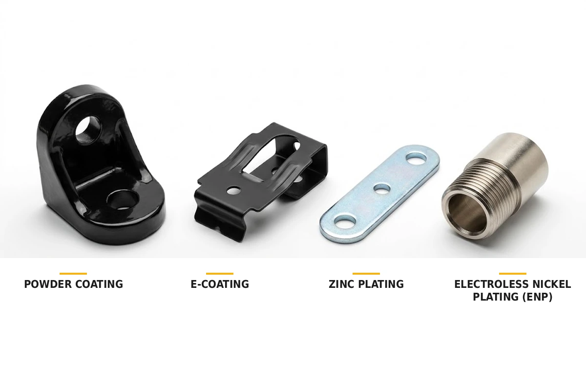
1. Powder Coating
- Dimensional Impact: The coating is exceptionally thick and consumes significant clearance, with industrial standard thicknesses typically ranging from 60 to 120 µm.
- DFM Strategy: Masking is strictly required for all threaded holes, guide rails, and precision mating surfaces on the engineering drawing (e.g., using high-temperature silicone plugs). Without masking, the cured powder will completely prevent fastener installation.
2. E-Coating (Electrophoretic Painting)
- Dimensional Impact: Compared to powder coating, the E-coat film is very thin and highly uniform, typically adding only 15 to 35 µm.
- DFM Strategy: Because the coating is thin and can easily penetrate complex internal cavities, the risk of mating interference is much lower. It serves as an excellent anti-corrosion primer for complex stampings and internal sheet metal brackets.
3. Electroless Nickel Plating (ENP)
- Dimensional Impact: Based on ASTM B733 service conditions, standard engineering anti-corrosion applications typically require a thickness of 13 to 25 µm (corresponding to SC2/SC3 minimum thickness requirements).
- DFM Strategy: Unlike standard electroplating, ENP does not rely on external electrical currents, allowing for exceptional coating uniformity. However, this uniformity still depends on the plating solution's ability to circulate fully within deep holes or internal cavities. Fluid exchange difficulties must be evaluated for slender blind holes. During the design phase, this thickness can be accurately factored directly into the mating tolerances.
4. Zinc Plating (Electrogalvanizing)
- Dimensional Impact: Coating thickness typically ranges from 5 to 25 µm. Because current density is not uniform across complex geometries, zinc plating tends to build more heavily on exposed edges and corners, while deep recesses and blind holes may receive less coating.
- DFM Strategy: Hydrogen embrittlement risks must be strictly managed. According to ASTM B633-23, high-strength steels with tensile strengths exceeding 1700 MPa should not be electroplated according to this standard. High-strength steel is highly susceptible to hydrogen embrittlement fractures during electroplating. Material strength grades must be explicitly evaluated on the drawing; if standard electroplating is unsuitable, alternative anti-corrosion solutions must be specified.
II. Surface Conversion: Inward Penetration and Outward Growth
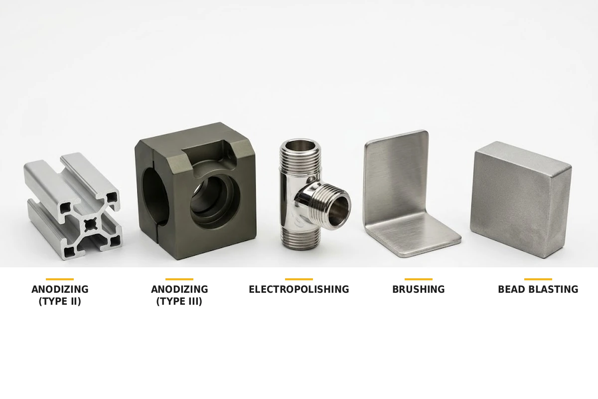
5. Anodizing
Anodizing does not "paint" a coating onto the surface; rather, it uses an electrochemical reaction to convert the surface aluminum into a dense aluminum oxide layer.
- Dimensional Impact & The 50/50 Rule: The oxide layer grows by penetrating the base material while simultaneously building outward. The rule of thumb that "approximately half the thickness grows outward, and the other half penetrates the substrate" serves as a practical approximation for initial estimates under typical process conditions. Note that the thickness ratio inside deep holes and narrow features may differ from exterior surfaces.
- OD vs. ID Tolerance Calculation: Assuming MIL-PRF-8625 Type III Hard Anodizing with a specified nominal thickness of 50.8 µm (0.002 inches):
- The outward growth is approximately 25 µm per surface.
- For an Outside Diameter (OD), adding 25 µm per side means the total OD may increase by approximately 50 µm.
- For an Inside Diameter (ID), the hole wall grows 25 µm toward the center per side, meaning the total ID may decrease by approximately 50 µm.
Note: This is a theoretical calculation example; final acceptance dimensions must be verified with the surface finishing supplier.
III. Material Removal: Processes That Reduce Dimensions
6. Electropolishing
The workpiece acts as the anode in an electrified electrolyte bath, where microscopic surface peaks dissolve preferentially, resulting in a smooth, bright finish.
- Dimensional Impact: Electropolishing is a subtractive process. According to references like the NASA PRC-5009 specification, electropolishing typically removes 0.0002 to 0.0005 inches (approx. 5 to 13 µm) of material per surface. This range is a baseline reference; actual material removal depends on the specific material, process parameters, and drawing requirements, fluctuating slightly based on electrode positioning and part geometry.
- DFM Strategy: This process will inevitably reduce shaft diameters and enlarge hole diameters. If medical or food-grade stainless steel parts require strict interference or transition fits, this material removal allowance must be pre-calculated in the drawing's dimensions.
IV. Texture Adjustment: Processes That Modify Roughness
7. Brushing (Hairline Finish)
- Dimensional Impact: Macroscopic dimensional material removal is minimal (usually negligible), but it modifies the surface roughness (Ra) and creates a unidirectional linear texture.
- DFM Strategy: Used primarily for stainless steel and aluminum cosmetic parts. The brushing direction must be explicitly indicated on the drawing. An anti-fingerprint coating is highly recommended to protect the final surface.
8. Bead Blasting / Sandblasting
- Dimensional Impact: Does not alter macroscopic tolerances, but creates a uniform matte/satin texture. For thin-walled parts or components already at their dimensional limits, critical dimensions and mating surfaces must still be verified post-blasting.
- DFM Strategy: Blasting is an excellent surface roughening prep-step before powder coating or anodizing to significantly enhance adhesion. However, aggressive blasting will destroy the original surface finish of precision CNC machined areas. Masking requirements for critical sealing surfaces must be clearly stated on the drawing.
Comprehensive Case Study: Precision Aluminum Optoelectronic Housing
To better understand how dimensional chains interact with process selection, let's examine a representative engineering case:
- Design Requirements: An outdoor optoelectronic sensor housing CNC machined from 6061 aluminum. The exterior requires extreme wear and corrosion resistance; the interior must remain electrically conductive for EMI shielding; the housing features multiple M3 threaded holes for assembling precision circuit boards.
- Process Combination & DFM Execution:
- Exterior: Selected MIL-PRF-8625 Type III Hard Anodizing to generate a roughly 50 µm oxide layer for maximum wear resistance.
- Tolerance Compensation: During the CNC machining phase, critical external mating dimensions were intentionally machined approximately 25 µm undersized to offset the outward volumetric growth of the hard anodizing.
- Masking Interiors & Threads: Prior to anodizing, custom acid-resistant silicone plugs were used to strictly mask the internal conductive cavities and all M3 threaded holes.
- Final Result: The exterior achieved a high-hardness protective layer falling perfectly within the tolerance band; the interior retained its required conductivity; the M3 threads were unaffected by the "inward growth" that normally shrinks hole diameters, ensuring smooth fastener assembly.
Engineer's Quick Reference: Dimensional Tolerance Matrix
The coating thicknesses and material removal amounts listed in this table are industry reference ranges and do not represent a fixed manufacturing capability or universal acceptance guarantee for all parts. Actual dimensional changes are heavily influenced by part geometry, process parameters, substrate condition, and masking strategies.
| Category |
Process Name |
Typical Thickness / Removal |
Dimensional Impact (DFM Key Points) |
| Coating & Deposition |
1. Powder Coating |
60 - 120 µm |
Thick coating taking up significant clearance. Masking is strictly required for threads and precision fits. |
| Coating & Deposition |
2. E-Coating |
15 - 35 µm |
Uniform and very thin. Ideal for complex stampings/sheet metal with low risk of interference. |
| Coating & Deposition |
3. Electroless Nickel (ENP) |
13 - 25 µm |
Exceptionally uniform, but requires sufficient fluid circulation within internal cavities. |
| Coating & Deposition |
4. Zinc Plating |
5 - 25 µm |
Coating distribution depends on current-density distribution across the geometry. High-strength steels require strict evaluation of hydrogen embrittlement risks. |
| Surface Conversion |
5. Anodizing (Type II / Type III) |
Type II: 5 - 25 µm; Type III: approx. 50 µm |
Bi-directional growth. OD increases and ID decreases; precision mating surfaces require allowances or masking. |
| Material Removal |
6. Electropolishing |
Subtractive: 5 - 13 µm / surface |
Decreases shaft diameters and enlarges hole diameters. CNC phase must leave material allowance. |
| Texture Adjustment |
7. Brushing (Hairline Finish) |
No fixed thickness |
Macroscopic dimensional impact is minimal; primarily alters surface roughness and creates directional texture. |
| Texture Adjustment |
8. Bead Blasting / Sandblasting |
No fixed thickness |
Macroscopic dimensional impact is generally minor; aggressive blasting can affect edges and precision surfaces. |
Need Surface Finishing and DFM Support?
Selecting the correct surface finishing process dictates far more than anti-corrosion grades—it is the core link to ensuring high assembly yield rates for metal parts. If you are unsure whether your drawing tolerances can accommodate a specific coating, or if you need to find a more cost-effective process combination, contact Tongyong . Our team of manufacturing engineers is ready to provide you with professional DFM reviews and manufacturing quotes.
Technical Reference Standards
The data and specification recommendations in this article are structured around the following mainstream international materials and process standards:
- MIL-PRF-8625F w/ Amendment 2: Anodic Coatings for Aluminum and Aluminum Alloy.
- NASA/JSC PRC-5009 Rev. C: Electropolishing of Corrosion-Resistant Steel & Nickel-Based Alloys.
- ASTM B633-23: Standard specification for electrodeposited coatings of zinc on iron and steel (contains Section 1.4 restriction statements regarding ultra-high-strength steel). (View ASTM Standard)
- ASTM B733-22(2026): Standard specification for autocatalytic (electroless) nickel-phosphorus coatings on metal. (View ASTM Standard)
 Have a Custom Manufacturing Project?