The powder coating vs anodizing decision is often reduced to color and price. That approach can overlook issues that later cause poor fit, grounding problems, cosmetic variation, or unexpected finishing costs.
Anodizing and powder coating do not interact with aluminum in the same way. Anodizing forms an oxide coating from the aluminum surface, while powder coating applies and cures a separate organic film over the metal.
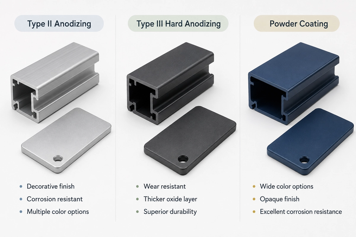
There is also more than one relevant category of anodizing. Decorative or protective sulfuric anodizing and hard anodizing serve different project priorities. A useful anodizing vs powder coating comparison should therefore distinguish among:
- Type II sulfuric-acid anodizing;
- Type III hard anodizing;
- powder coating.
The Type II and Type III terms used in this article follow the MIL-PRF-8625 classification system. ISO terminology may differ. ISO 7599:2018 applies to decorative and protective anodizing, while hard anodic coatings used mainly for engineering purposes are addressed separately by ISO 10074.
Powder Coating vs Anodizing: Three Options, Not Two
| Decision factor |
Type II decorative/protective anodizing |
Type III hard anodizing |
Powder coating |
| Main purpose |
Appearance, general protection, and retention of metallic character |
Wear, electrical insulation, and other engineering requirements |
Color, texture, and organic protective coating |
| Relationship to aluminum |
Oxide coating formed from the aluminum surface |
Thicker engineering oxide coating formed from the surface |
Separate cured organic film applied over the surface |
| Appearance |
Alloy, pretreatment, machining, and dye influence the result |
Color and roughness may vary more; cosmetic uniformity is not normally evaluated like decorative anodizing |
More opaque coverage with a broad range of colors, gloss levels, and textures |
| Thickness |
Defined by the drawing and applicable standard |
Defined by the drawing and applicable standard; often substantially thicker than decorative anodizing |
Defined by the powder system and project specification |
| Dimensional effect |
Coating growth still requires consideration |
More significant for bores, fits, threads, and precision features |
Each coated wall occupies the actual cured-film thickness |
| Electrical contact |
Anodic oxide is insulating |
Hard anodic oxide is insulating |
Conventional organic powder coatings are generally insulating |
| Deep features |
Internal coating may differ from open surfaces |
Deep or narrow features require detailed process review |
Recesses and inside corners may be affected by the Faraday cage effect |
| Heat exposure |
No powder-curing oven cycle |
No powder-curing oven cycle |
The cure schedule must be compatible with the material condition, inserts, seals, adhesives, and assemblies |
| Damage and repair |
Damage may expose the substrate; exact cosmetic restoration is difficult |
Damage should be evaluated functionally rather than treated like ordinary paint damage |
Impact or poor preparation may cause chipping or adhesion failure; touch-up may not match the original gloss and texture |
ISO 18768-1:2022 covers methods for specifying decorative and protective powder coatings on aluminum and its alloys. Its requirements are connected to the intended application and the aggressiveness of the service environment.
The table provides an initial direction rather than a universal performance ranking. The final result still depends on the alloy, pretreatment, coating specification, geometry, process control, and operating conditions.
Appearance, Damage, and Maintenance
Type II anodizing
Type II is usually the more relevant anodizing option when a customer wants a metallic aluminum appearance, a clear or colored finish, and general protective performance.
Anodizing follows the underlying surface instead of leveling it. Machining lines, brushing direction, weld zones, polishing variation, and alloy differences may remain visible after treatment.
NASA’s PRC-5006 anodizing process specification notes that the original surface texture is replicated rather than leveled. A bright anodized appearance therefore requires an appropriately prepared starting surface, while a matte result may require blasting or another controlled pretreatment.
This means that poor cosmetic preparation cannot be corrected simply by requesting anodizing. The alloy, machining condition, brushing direction, weld appearance, and cosmetic surfaces should be reviewed before finishing.
Type III hard anodizing
Type III is primarily an engineering treatment. Wear behavior, electrical insulation, coating thickness, final dimensions, and functional testing are usually more important than decorative color consistency.
The Aluminum Anodizers Council Hardcoat Anodizing Guideline lists 2 mil (0.002 in, approximately 50.8 μm) as a reference requirement when no other thickness is specified. NASA PRC-5006 uses 0.0020 ± 0.0004 in as its own source-specific default for Type III coatings.
These values belong to the cited documents. They are not universal requirements for every hard-anodized component. Actual coating thickness must follow the customer drawing, contract, and governing standard.
Hard anodizing should not be selected only because it sounds more durable. Its greater thickness, roughness, color variation, and dimensional effect may make it unsuitable for a cosmetic enclosure that primarily requires an attractive metallic finish.
Powder coating
Powder coating generally provides broader color, gloss, and texture options and a more opaque visual result. It can reduce the visibility of minor substrate color differences, but it cannot compensate for oil, contamination, incomplete pretreatment, poor weld preparation, or unsuitable surface condition.
The selected powder chemistry must also match the operating environment. A powder system intended for indoor use should not automatically be treated as equivalent to one designed for long-term outdoor ultraviolet and weather exposure.
Powder coating requires a curing cycle. The specified metal temperature and holding time must be compatible with:
- the aluminum alloy and material condition;
- threaded inserts and press-fit hardware;
- seals and plastic components;
- adhesives;
- heat-treated parts;
- previously assembled components.
Damage and maintenance should also be considered. An anodic coating and a separate organic powder film do not fail in the same way.
Powder-coating touch-up may protect a locally exposed area, but the repaired color, gloss, or texture may not exactly match the original coating. Cosmetic damage to anodized aluminum is also difficult to restore locally without visible variation.
For an overview of the available finishing options, see our surface finishing capabilities.
DFM Requirements for Anodized and Powder-Coated Parts
Dimensions, threads, grounding areas, masking, racking, and geometry should be reviewed before the manufacturing drawing is released.
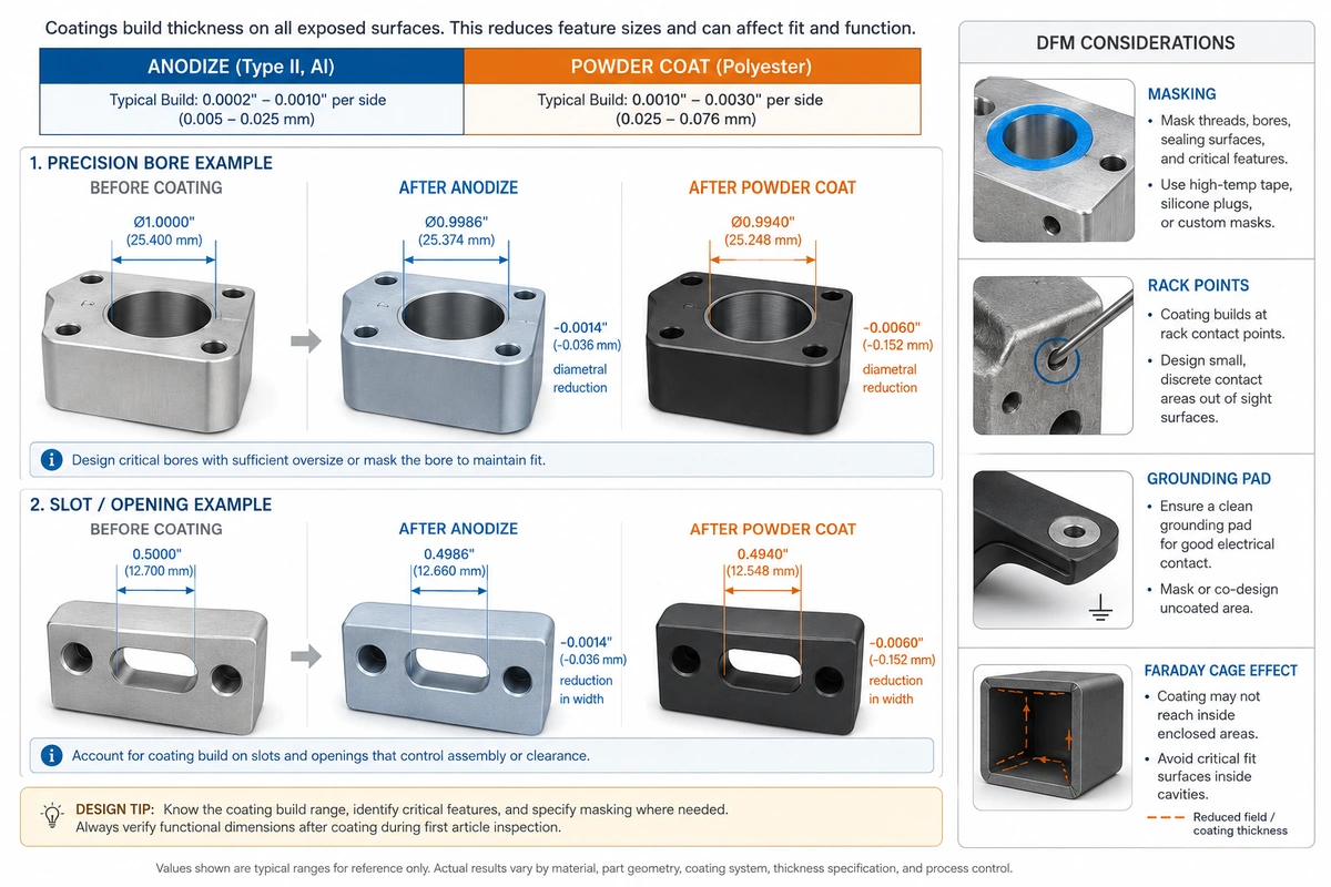
Example 1: Type III hard-anodized bore
Assume a precision bore is machined to:
10.000 mm
For this example only, assume:
- nominal hard-anodic coating thickness: 50 μm;
- approximately half of the coating contributes to outward surface growth;
- estimated growth into the bore from each wall: 25 μm.
The estimated finished opening is:
10.000 mm − 0.025 mm − 0.025 mm = 9.950 mm
This calculation is useful for preliminary DFM, but 9.950 mm is not an acceptance dimension.
NASA PRC-5006 states that approximately half of a Type III coating penetrates the original surface and half contributes to outward growth. It also notes that internal and external coating thicknesses may differ and that coating thickness may decrease in narrow or deep holes.
The final drawing should define:
- the required post-finish dimension;
- dimensional tolerance;
- measurement method;
- whether masking is permitted;
- whether post-finish machining is permitted.
A nominal coating calculation cannot replace a clearly specified final dimension and inspection method.
Example 2: powder-coated opening
Assume a slot is designed at:
20.00 mm
The hypothetical project specification calls for a 60 μm cured film on each coated wall.
The estimated clear opening becomes:
20.00 mm − 0.06 mm − 0.06 mm = 19.88 mm
The 60 μm value is a project assumption, not a universal powder-coating standard. The actual film-thickness requirement must come from the selected powder system or customer specification.
Deep recesses, inside corners, and narrow passages may experience the Faraday cage effect, making it difficult for electrostatically charged powder to enter or build evenly.
Internal coverage should therefore be confirmed through a sample, process trial, or first-article inspection rather than inferred from an external flat surface.
Threads, fits, and masking
Hard anodizing can alter thread pitch diameter, flank clearance, and surface roughness. Whether threads may be anodized should be determined by the governing standard, coating thickness, thread class, and assembly requirement.
NASA PRC-5006 does not recommend hard anodizing thread surfaces within its own process scope. This should not be treated as a universal prohibition for every industry or application.
Other specifications or particular applications may permit thinner coatings, but deliberate control is still required through:
- masking;
- machining allowance;
- adjusted tooling dimensions;
- oversize tapping;
- post-finish adjustment.
The same DFM logic applies to bearing seats, press fits, sealing faces, connector openings, and close-tolerance sliding features.
Grounding and rack marks
Anodizing requires electrical contact between the part and the rack. The contact position can leave a small uncoated area, so acceptable contact points—or surfaces where contact is prohibited—should be identified on the drawing.
Electrostatic powder coating also requires reliable grounding. The hook or fixture must make conductive contact with the part, and the contact position may remain partially uncoated or show a local mark.
The RFQ and drawing should therefore identify:
Acceptable anodizing or powder-coating rack points, contact points, and local uncoated areas.
Electrical bonding surfaces require similar attention. Both anodic oxide and conventional organic powder coatings are normally electrically insulating, so grounding pads and conductive contact areas may require masking.
Our aluminum extrusion services and sheet metal fabrication capabilities cover products whose geometry, joints, openings, and manufacturing routes may affect the finishing result.
What Drives Finishing Cost?
It is not reliable to state that anodizing or powder coating is always less expensive.
| Anodizing cost driver |
Powder-coating cost driver |
| Aluminum alloy and material condition |
Pretreatment system |
| Type II or Type III |
Indoor or outdoor powder chemistry |
| Coating thickness |
Color, gloss, and texture |
| Dye and sealing requirements |
Color-change and minimum-batch cost |
| Rack locations and masking quantity |
Part size and oven capacity |
| Cosmetic grade and permitted color variation |
Cure schedule and component heat compatibility |
| Testing and inspection |
Masking, grounding, film thickness, and inspection |
| Batch quantity and part geometry |
Batch quantity and rework risk |
A low unit price can become misleading when a project requires extensive masking, an unusual color, several rack changes, close-tolerance inspection, sample approval, or difficult rework.
Cost should therefore be compared using the complete approved process rather than only the finish name.
For example, a simple Type II anodized extrusion in a standard finish may have a very different cost structure from a cosmetic machined enclosure requiring color control, concealed rack marks, and multiple masked features.
Similarly, a standard powder-coated bracket may be straightforward, while a large enclosure with a custom texture, many threaded holes, grounding areas, and strict cosmetic acceptance can require substantially more preparation and handling.
Which Finish Fits Your Aluminum Part?
| Project situation |
More likely starting point |
Reason |
| Machined aluminum enclosure that should retain metallic character |
Type II anodizing |
Retains more of the underlying aluminum appearance |
| Precision wear component |
Type III hard anodizing |
Wear, insulation, and other engineering properties may matter more than decorative appearance |
| Branded enclosure requiring an opaque color and texture |
Powder coating |
Provides a wider cosmetic range and stronger visual coverage |
| Welded aluminum assembly requiring a more uniform opaque appearance |
Powder coating may be evaluated first |
Anodizing may reveal differences between weld metal and parent material |
| Part with tight bores, press fits, or bearing seats |
Detailed DFM review before selection |
Both anodizing growth and powder film may affect fit |
| Outdoor aluminum housing |
Depends on the exact specification |
Alloy, pretreatment, sealing, powder chemistry, ultraviolet exposure, moisture, and damage risk all matter |
| Part with electrical bonding areas |
Either process with defined masking |
Both finishes normally insulate contact areas |
| Deep cavities and narrow inside corners |
Sample verification required |
Internal anodizing thickness and powder coverage may differ from open surfaces |
This table provides a starting direction, not a universal rule.
The aluminum alloy and manufacturing route should be confirmed before selecting the finish. Extruded profiles, machined parts, sheet-metal enclosures, castings, and welded assemblies may respond differently.
Projects involving several manufacturing operations may also benefit from reviewing our broader custom metal manufacturing services.
RFQ Checklist for Powder-Coated and Anodized Parts
| Information |
What to state |
| Material |
Aluminum alloy, temper, and manufacturing route |
| Anodizing |
Governing standard, Type II or Type III where relevant, class, color, sealing, and coating requirement |
| Powder coating |
Powder system, indoor or outdoor use, color, gloss, texture, and cure restrictions |
| Cosmetic requirement |
Visible surfaces, acceptable color variation, weld appearance, and approved sample |
| Dimensions |
Post-finish bores, threads, fits, sealing faces, and connector openings |
| Masking |
Grounding pads, threads, bearing seats, sealing surfaces, and conductive areas |
| Racking |
Acceptable hook, rack, contact, or local uncoated positions |
| Environment |
Moisture, salt, ultraviolet exposure, chemicals, abrasion, and temperature |
| Inspection |
Thickness, color, gloss, adhesion, corrosion test, and first-article approval |
| Quantity |
Prototype, low-volume, or production quantity |
A useful quotation request should describe what the finished part must do, rather than specifying a finish only by appearance.
For example:
Outdoor aluminum enclosure requiring a low-gloss dark-gray appearance, masked grounding pads, threaded inserts, and connector openings controlled after finishing.
This gives the manufacturer enough information to review the finish, powder or anodizing specification, masking plan, tolerance strategy, racking method, and inspection requirements.
Review our surface finishing capabilities and custom metal manufacturing services for related production options.
To receive a project-specific review, send us your aluminum part drawings and finishing requirements.
 Have a Custom Manufacturing Project?